

ADVERTISEMENT
Radial Intracardiac Echocardiographic Imaging for Atrial Fibrillation Ablation
The use of intracardiac echocardiography (ICE) as an adjunct to procedures in cardiac electrophysiology has allowed operators to obtain real-time, three-dimensional anatomical information. Over the years, the evolution of procedures for the ablation of atrial fibrillation has led us to our present approach of pulmonary vein isolation with or without additional atrial substrate modification. To a great degree, these procedures are anatomically driven. Therefore, precise anatomical information is paramount to the successful completion of the ablation. A variety of technologies have been employed to provide anatomical information to the operator. The standard approach is fluoroscopy. While this provides real-time information, the anatomical detail provided is limited. Supplementation of fluoroscopic images with electroanatomical mapping system data has been extremely useful. These systems can be coupled with three-dimensional anatomical data from CT scans or magnetic resonance imaging, and provide very detailed anatomy to help guide the operator in the ablation. Unfortunately, these images are static, and are acquired at a time different than the time of the actual catheter ablation procedure. In addition, there can be challenges with image registration and anatomical alignment. This can result in inaccurate anatomical rendering and lead to shifts in anatomy during the case, with resultant inaccuracy of catheter positioning relative to the anatomy. Clearly, a technology that can provide real-time detailed anatomical information should be valuable for atrial fibrillation. ICE imaging fits those criteria.
Radial ICE Imaging
There are two general types of ICE technologies being used today. The more popular technology used is phased array imaging on a steerable catheter platform. This generates images similar to those acquired with transesophageal echocardiography, and hence, the images are relatively familiar to operators with some degree of general echocardiography training. The advantages of this technology are that one has good far-field resolution, and imaging of the left atrium can be performed from right atrial catheter positions. The disadvantage of this approach is that the image resolution can sometimes be limited, tissue characteristics are not well discerned distant from the transducer, and the imaging sector sometimes moves across the catheter as the heart beats, leading to a somewhat unstable image.
The opposing technology is radial ICE imaging. With this technology, the transducer mechanically rotates in the tip of the catheter and the image that is generated is circular, with the transducer in the center of the image. Radial ICE imaging generates very clear near-field images, but is less useful for imaging 2–3 cm from the catheter and beyond. For that reason, the catheter needs to be introduced into the chamber of interest to achieve high-resolution imaging. An advantage of this approach is that the imaging catheter moves in concert with the heart, and the ablation catheter provides a stable image that allows the operator to precisely track the motion of the ablation catheter and the tissue targeted for ablation. A disadvantage is that the catheter needs to be introduced into the left atrial chamber. If the operator employs two transseptal sheaths during pulmonary vein isolation procedures, one sheath is occupied by the ablation catheter and the second is occupied by the imaging catheter. Therefore, introduction of a circular mapping catheter either requires a third transseptal puncture or multiple catheter exchanges during the course of the procedure. Another limitation of radical ICE imaging is that the imaging plane is determined by the course of the imaging catheter. Depending upon the patient’s anatomy, it is not uncommon to acquire off-axis images that result in displays that are not analogous to any standard transthoracic or transesophageal echo displays. For example, when one is imaging with a catheter passing from IVC to SVC, the imaging plane is a transverse (cross-sectional) plane that presents the cardiac anatomy in a fairly familiar context. However, if the imaging catheter is within a sheath that crosses a transseptal puncture into the left atrium, the imaging plane transitions from transverse cross-sectional to an angled coronal plane. This view is unfamiliar to most operators and requires substantial experience in order to easily identify anatomical landmarks. Along with this challenge, the radial ICE transducer can be rotated in a 360º fashion, and often rotates as the catheter is advanced through the heart. Therefore, not only can the imaging plane be atypical, but if familiar landmarks are not identified, it is possible that the operator may inadvertently view images rotated 180º out of standard orientation. It is therefore paramount that anatomical landmarks be identified and that the imaging is performed using standard views.
Standard Views
Right Atrial Imaging
The standard view for the right atrium is a transverse cross-sectional view with the catheter oriented in an inferior-superior axis. The standard orientation shows the image with the anterior atrium at 12 o’clock, posterior atrium at 6 o’clock, the interatrial septum at 3 o’clock, and the right atrial free wall at 9 o’clock. As one advances the catheter from inferior to superior, the IVC opens into the left atrial body with clear imaging of the Eustachian valve. Just superior to that point, the coronary sinus ostium and the inferior arc of the tricuspid valve are revealed. Advancing the catheter somewhat further brings the fossa ovalis, mid tricuspid valve, and atrial body into view. Continuing to advance the catheter will allow visualization of the right atrial appendage, the head of crista terminalis (the sinus node), and then ultimately the catheter can be advanced into the superior vena cava. The crista terminalis can be imaged throughout its course in atrium.
Transseptal Catheterization Imaging
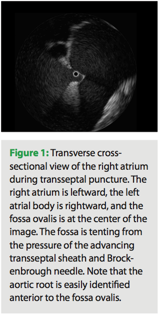 When one is performing a transseptal puncture, the tip of the imaging catheter can be placed directly in the fossa ovalis below the superior course of the limbus. The imaging in the position is often off-axis as the catheter axis changes from inferior-superior to a more right-left transverse orientation. Depending on the actual course of the catheter, the image may show a clear view of the fossa with the right atrium in the left field of view and the left atrium in the right field of view (Figure 1). If the catheter axis is more right-left, then one may see a cross-sectional view of the fossa and the limbus. The view may resemble the “hole in the doughnut.” With an angled view, one may image through the floor at the left atrium and not visualize the left atrial chamber. The aortic root is usually easily seen just anterior to the fossa. Avoiding this anatomical structure during transseptal puncture is easily achieved with ICE guidance.
Left Atrial Imaging
 The standard views of the left atrium are acquired with the catheter passing transversely from the atrial septal crossing to the lateral atrium, either the left atrial appendage, or more commonly, the left pulmonary vein. The orientation in this modified coronal view shows the superior left atrium at 12 o’clock, the anterior left atrium at 3 o’clock, the inferior left atrium (posterior to mitral annulus) at 6 o’clock and the posterior wall at 9 o’clock. Because the imaging catheter follows a right-to-left, inferior to superior course through this chamber,
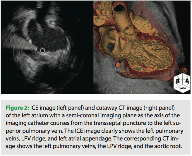
 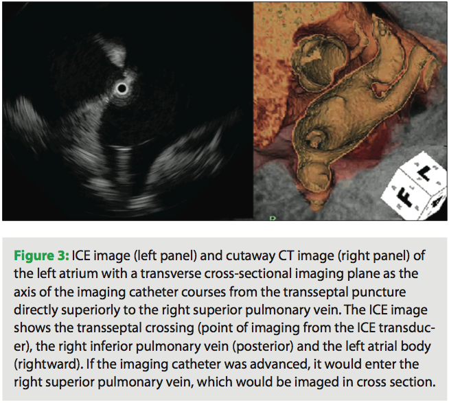 the image is not a true coronal projection (Figure 2). Proper orientation of the catheter is important as it is easy to misinterpret images if the rotation of the transducer is not correct. Landmarks that are easy to identify are the aortic root and mitral valve. The aortic root is a more septal structure and should be positioned in the right side of the image with a vertical orientation. Slightly lateral to the aortic root is the mitral valve. This image should be in the lower right quadrant of the image. As one advances the imaging catheter laterally, the atrium of the left pulmonary vein comes into view. If the catheter is advanced into the left pulmonary vein, the ridge is easily identifiable, and defines the transition from LPV into the base of the left atrial appendage. The appendage is trabeculated and contractile, and may be identified by its morphology and relationship to the left pulmonary vein. Right pulmonary vein imaging is accomplished by rotating the curved ICE introducer sheath in a clockwise fashion. The imaging catheter will sweep along the posterior left atrial wall and naturally seat itself in the right superior pulmonary vein (Figure 3). On fluoroscopy, it is now obvious that the imaging catheter has returned to an inferior-superior axis. The proper location of the catheter in the RSPV is easily confirmed by identifying the landmarks of the superior vena cava and right pulmonary artery. These three circular structures form a triangle. If these vessels are not easily identified, then it is likely that the catheter is in a right-middle lobe branch or possibly the right-inferior pulmonary vein. Orientation of the imaging catheter should be such that the anterior left atrium and RSPV is at 12 o’clock, the RSPV will open into the left atrial body at 3 o’clock, the RIPV will have a near-perpendicular take off to the imaging axis at 6 o’clock, and the intra-arterial septum will be at 9 o’clock.
Right Ventricular Imaging
When the imaging catheter makes a transition from the right atrium to the right ventricle, the axis of the catheter changes to a posterior-anterior axis. The transducer should be rotated so that the superior RV is at 12 o’clock, the RV free wall is at 3 o’clock, the inferior wall is at 6 o’clock, and the intraventricular septum is at 9 o’clock. As one advances the catheter into the RV, the imaging plane is parallel to the tricuspid annulus, and therefore, the valve opening is imaged in a circular pattern around the central transducer. The catheter can be advanced into the RV apex, which is highly trabeculated. Although it is possible to image the left ventricle from the right side of the septum, the poor penetration at greater depths precludes high-resolution imaging of that chamber. If the introducer sheath is rotated in a clockwise fashion after crossing the tricuspid valve, the catheter can be advanced through the RV outflow track into the pulmonic valve. Once again, the imaging is returned to an inferior-superior axis, with the resulting image being a transverse cross section.
Left Ventricular Imaging
The left ventricle is best imaged by inserting the catheter into a curved introducer sheath across a transseptal puncture. The curved introducer sheath can be rotated into an anterior orientation (counterclockwise) and oriented toward the mid-mitral orifice. The imaging catheter then can be advanced straight across the valve to the right ventricular apex. Conventional orientation of this image usually has the anterior wall at 12 o’clock, the interatrial septum at 3 o’clock, the posterior at 6 o’clock, and the lateral wall at 9 o’clock. Left ventricular ICE imaging can be used to delineate the anatomical boundaries of an aneurysm, and can help guide catheter movement around structures such as the papillary muscles. Of note, imaging from within the left ventricle can be performed rapidly during the course of atrial fibrillation ablation if pericardial tamponade is suspected.
ICE-Guided Procedures
Transseptal Catheterization
When performing transseptal catheterization under ICE guidance, it is useful to insert the ICE catheter through a sheath with a moderate (55–90º) curve. The tip of the ICE catheter can be extended from the tip of the introducer sheath, and the sheath can be rotated to direct the catheter to the fossa ovalis. Ultimately, the fossa ovalis can be engaged by the tip of the imaging catheter (Figure 1). Once the ICE catheter is in position, the operator can proceed with standard engagement of the fossa with the transseptal sheath and Brockenbrough® needle (Medtronic). The ICE imaging crystal can be used as a fluoroscopic target for transseptal needle positioning. When the transseptal needle is fully engaged in the fossa ovalis, this thin muscular wall shows tenting. The left atrial chamber beyond the septum can be easily visualized and the angle of the transseptal needle may be adjusted to assure that the crossing occurs in the mid portion of this chamber. In addition, after puncture has been performed, the course of the transseptal catheter may be imaged, and the possibility of back wall puncture of the left atrium can be assessed. After one sheath has been placed in the left atrium via transseptal access, the ICE catheter can be withdrawn from the first sheath and advanced through the second sheath for imaging of the fossa ovalis during a second transseptal puncture. As any experienced AF ablation operator will profess, there is no greater impediment to progression of catheter manipulation in the left atrium by beginners than fear of losing the transseptal access. However, with ICE guidance, manipulation of the ablation catheter across the previously established transseptal puncture site is usually rapid and fairly straightforward.
Left Pulmonary Vein Antrum Ablation
In order to facilitate imaging of the left pulmonary veins, it is usually advisable to first advance the ICE catheter deep into the left superior pulmonary vein and then advance the introducer sheath over this catheter. The ICE catheter can then be withdrawn into the sheath and the vein imaged through the sheath wall. This approach allows for a stable imaging pathway as the imaging plane is advanced into the vein and back out into the antrum and left atrial body. A slightly different viewing angle can be achieved if the sheath is positioned in the left inferior pulmonary vein. An extraostial ablation strategy will require antral ablation of the posterior wall with the ICE imaging plane located more proximally, and then isolation of the ridge portion with advancement of the imaging catheter about 1 cm. When one is imaging the ablation catheter on the ridge, it is common for the catheter to slide to the appendage side of the ridge to the vein side of the ridge. Since the ridge is relatively thick, it is advantageous to ablate on both sides of the ridge as well as on its apex if possible. Note that the ablation electrode tip is easily identified by its highly echogenic ring-down artifact. It is common to view the esophagus somewhere in the region of posterior wall ablation. Since the esophagus is relatively wide, it is virtually impossible to get complete extraostial ablation of the left pulmonary veins without performing some limited ablation directly over the esophagus. When one is ablating directly over the esophagus with little interposed atrial or interstitial tissue as assessed by ICE, it is recommended that the operator limit both power and ablation time. After completion of the ablation line, one can access adequacy of vein isolation using ICE-guided point-to-point mapping around the circumference of the superior and inferior veins. In addition, one can pace from multiple sites within the vein to assure that there is exit block. If one conducts from LSPV to the atria with pacing at high output (>10 mA), one must consider the possibility of far-field capture of the left atrial appendage. This question may be elucidated by ICE catheter imaging. Far-field pacing occurs with the catheter tip immediately contiguous to the appendage. Capture is lost if the catheter is moved a few millimeters in one direction or another.
Right Pulmonary Vein Antrum Ablation
In order to best image during right pulmonary vein isolation, the sheath is advanced into the right superior pulmonary vein, as described above. The ICE catheter is advanced deep into the right superior pulmonary vein, and the sheath is advanced over this catheter. From that point forward, the right pulmonary veins are imaged by advancing and withdrawing the ICE catheter within the sheath. Thus, the full range of right pulmonary vein anatomy can be visualized without risk of losing the transseptal crossing. The generation of the anteroseptal ablation line can be tracked by moving the imaging catheter as the ablation catheter is moved forward and back in a superior-inferior motion. The inferior component of the extraostial line is sometimes best achieved by ablating directly at the right inferior pulmonary vein ostium. The posterior line is best generated at the convex transition from the right inferior pulmonary vein to the left atrial body. It is sometimes challenging to maintain the gentle torque required to ablate on this curved surface. The movement of the catheter in this line can be imaged in real time by the ICE catheter to assure contiguous lesions. To complete the superior extraostial ablation, the catheter is advanced straight up to the roof, and individual lesions are created in a line to connect the anterior and posterior portions of the encircling ablation. The esophagus is sometimes imaged lateral and contiguous to the right inferior pulmonary vein.
Substrate Modification
Typically, creation of linear ablation or ablation of complex atrial fractionate electrograms (CAFEs) is best achieved using electrogram and electroanatomical map guidance. However, this mapping information often benefits by supplementation with anatomical information from ICE. In particular, when the goal is to create conduction block at the mitral valve annulus, it is often difficult to exactly determine that anatomical boundary. ICE imaging provides the operator with precise guidance as to where the ablation line should begin and end. Also, if ablation is performed within the coronary sinus, the ICE image from the left atrium of the catheter tip position in the coronary sinus is a useful guide in connecting CS lesions to endocardial lesions at the mitral valve. ICE imaging is less helpful with ablation in the cavotricuspid isthmus for isthmus-dependent macroreentrant tachycardia due to the limited imaging planes that can be acquired. However, ICE is invaluable for ablation in and around the superior vena cava. The crista terminalis and sinus node region can be clearly imaged, and ablation strategies can be adjusted accordingly.
Conclusion
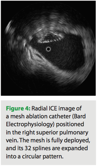 Radial ICE imaging is a useful adjunct to other methods of anatomical guidance for ablation of atrial fibrillation. It may be particularly helpful as new, innovative catheter technologies are introduced into the marketplace (Figure 4). In the future, global positioning devices may be coupled with radial ICE imaging catheters, and a 4D looping left atrial volume, continually updated by the real-time 2D information, may be rendered. Thus, a true representation of the beating atrium will be available to guide the operator to his/her anatomical target. Until that time, real-time radial ICE imaging offers valuable anatomical information to the operator, reducing procedure time and ultimately improving procedure success rates.


